
Core parameter classification and characteristics of inductors
2026-05-19
1. Core Parameters and Characteristics of Inductors
The performance of an inductor is determined by several key parameters, which directly affect its application effectiveness in circuits.
1.1: Inductance (L) --- Inductance is the fundamental parameter of an inductor, representing its ability to generate self-induced electromotive force.
The magnitude of inductance primarily depends on the following factors:
- Number of coil turns: The more turns, the greater the inductance.
- Core material: A coil with a core has greater inductance than one without a core; the higher the permeability of the core, the greater the inductance.
- Coil Structure: The larger the cross-sectional area of the coil, the greater the inductance; the shorter the length of the coil, the greater the inductance.
The formula for calculating inductance is: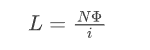
Among them, L is the inductance (H), N is the number of coil turns, Φ is the magnetic flux (Wb), and i is the current (A)
Among them, L is the inductance (H), N is the number of coil turns, Φ is the magnetic flux (Wb), and i is the current (A)
For the coil wound around the magnetic core, the inductance can also be expressed as: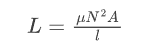
Among them, μ is the permeability of the magnetic core material, A is the cross-sectional area of the magnetic core, and l is the length of the magnetic circuit.
Among them, μ is the permeability of the magnetic core material, A is the cross-sectional area of the magnetic core, and l is the length of the magnetic circuit.
1.2: DC Resistance (DCR)
DC resistance (DCR) refers to the equivalent resistance of an inductor coil under DC conditions, determined by the wire material (such as copper, aluminum) and geometric structure (length, cross-sectional area) of the coil being wound. DCR is usually measured in milliohms (m Ω) and is an important parameter that affects inductance efficiency.
DC resistance affects the efficiency of BUCK circuit, and large DCR can cause heat loss, especially under heavy load conditions. In switch mode power supplies, inductors with smaller DCR are usually used to improve efficiency.
DC resistance (DCR) refers to the equivalent resistance of an inductor coil under DC conditions, determined by the wire material (such as copper, aluminum) and geometric structure (length, cross-sectional area) of the coil being wound. DCR is usually measured in milliohms (m Ω) and is an important parameter that affects inductance efficiency.
DC resistance affects the efficiency of BUCK circuit, and large DCR can cause heat loss, especially under heavy load conditions. In switch mode power supplies, inductors with smaller DCR are usually used to improve efficiency.
1.3: Rated current (Irms)
Rated current (Irms) refers to the maximum current value that an inductor can withstand under normal operating conditions. When the working current exceeds the rated current, the inductance will change its performance parameters due to heating, and may even burn out due to overcurrent.
Rated current (Irms) refers to the maximum current value that an inductor can withstand under normal operating conditions. When the working current exceeds the rated current, the inductance will change its performance parameters due to heating, and may even burn out due to overcurrent.
The rated current of power inductors is usually defined in two ways:
- Rated current based on self temperature rise: The rated current specification is based on the heat generation of the component. Using beyond this range may cause component damage and component failure.
- Rated current based on the rate of change of inductance value: The rated current specification is based on the degree of decrease in inductance value. When used beyond this range, IC control instability may occur due to an increase in ripple current.
1.4: Saturation current (Isat)
The saturation current (Isat) refers to the magnitude of the current flowing through an inductor when it reaches saturation. When the current increases to a certain extent, the magnetic field strength of the magnetic core reaches saturation, and the inductance begins to significantly decrease.
For inductors with magnetic cores, when the current increases to a certain extent, the magnetic field strength no longer increases. If the current continues to increase, the inductance of the device will rapidly decrease, and this current is called saturation current (Isat). Therefore, in order for inductors with magnetic cores to function properly, the peak current should not exceed the saturation current.
The saturation current (Isat) refers to the magnitude of the current flowing through an inductor when it reaches saturation. When the current increases to a certain extent, the magnetic field strength of the magnetic core reaches saturation, and the inductance begins to significantly decrease.
For inductors with magnetic cores, when the current increases to a certain extent, the magnetic field strength no longer increases. If the current continues to increase, the inductance of the device will rapidly decrease, and this current is called saturation current (Isat). Therefore, in order for inductors with magnetic cores to function properly, the peak current should not exceed the saturation current.
1.5: Self resonant frequency (SRF)
The self resonant frequency (SRF) is the natural resonant frequency of an LC resonant circuit formed by the distributed capacitance of the inductor (consisting of the capacitance between coil turns, layers, and between the wire and the magnetic core) and the inductance L.
The physical significance of SRF lies in:
- Operating frequency
- Operating frequency=SRF: impedance reaches maximum value (purely resistive)
- Operating frequency>SRF: Inductance exhibits capacitance (impedance Z ∝ 1/f)
1.6: Quality factor (Q value)
The quality factor (Q value) is the main parameter for measuring the quality of an inductor, which represents the ratio of the energy storage capacity to the loss capacity of the inductor component. The higher the Q value, the more efficient the inductor is in reducing electrical energy loss and magnetic energy leakage during energy storage.
The quality factor (Q value) is the main parameter for measuring the quality of an inductor, which represents the ratio of the energy storage capacity to the loss capacity of the inductor component. The higher the Q value, the more efficient the inductor is in reducing electrical energy loss and magnetic energy leakage during energy storage.
The high or low Q value is closely related to factors such as the material, thickness, multi strand or single strand wire, winding method, dielectric loss of the skeleton, high-frequency skin effect, presence or absence of magnetic core, and shielding cover of the inductor coil wire.
2. Classification and characteristic analysis of inductors
2.1 Types of inductors classified by structure and material
- Wire wound inductance: It is the most common type of inductance, consisting of copper wire wound around a magnetic core (ferrite, iron powder core, etc.).
Structural features: Copper wire wound on magnetic core (ferrite/iron powder core); The magnetic core material determines the high-frequency and saturation characteristics of the inductor; There are usually two types of structures: open and shielded.
Key parameters: Inductance value range: 1 μ H~100mH; Saturation current range: 1A~50A; DCR: Typically ranging from a few milliohms to several hundred milliohms.
Application scenarios: power conversion circuits (such as DC-DC converters); Motor drive circuit; Energy storage and filtering circuits; Power factor correction circuit.
Advantages and disadvantages: Advantages: Wide range of inductance, strong current carrying capacity, and good stability; Disadvantages: Large size, poor high-frequency characteristics, and possible electromagnetic interference.
Key parameters: Inductance value range: 1 μ H~100mH; Saturation current range: 1A~50A; DCR: Typically ranging from a few milliohms to several hundred milliohms.
Application scenarios: power conversion circuits (such as DC-DC converters); Motor drive circuit; Energy storage and filtering circuits; Power factor correction circuit.
Advantages and disadvantages: Advantages: Wide range of inductance, strong current carrying capacity, and good stability; Disadvantages: Large size, poor high-frequency characteristics, and possible electromagnetic interference.
- Stacked inductor: It is an inductor formed by stacking multiple layers of ferrite sheets with copper layers embedded in them.
Structural features: Multiple layers of ferrite sheets stacked, with copper layers embedded within; Leadless design reduces parasitic inductance; Surface mount (SMD) structure.
Key parameters: Inductance value range: 10nH~10 μ H; SRF:100MHz~10GHz; Rated current: usually between 0.1A~3A.
Application scenarios: RF circuits for mobile phones; High speed digital circuits; Wireless communication equipment; High frequency filtering and decoupling circuits.
Advantages and disadvantages: Advantages: small size, good high-frequency characteristics, low cost; Disadvantages: Limited current carrying capacity, narrow inductance range, poor heat dissipation performance.
Key parameters: Inductance value range: 10nH~10 μ H; SRF:100MHz~10GHz; Rated current: usually between 0.1A~3A.
Application scenarios: RF circuits for mobile phones; High speed digital circuits; Wireless communication equipment; High frequency filtering and decoupling circuits.
Advantages and disadvantages: Advantages: small size, good high-frequency characteristics, low cost; Disadvantages: Limited current carrying capacity, narrow inductance range, poor heat dissipation performance.
- Integrated inductor: It is an inductor made by die-casting magnetic powder and coil together.
cStructural features: Integrated die-casting of magnetic powder and coil; Fully enclosed magnetic circuit design, strong anti-interference ability; Flat wire winding technology reduces DC resistance.
Key parameters: Inductance value range: 0.1 μ H~100 μ H; Saturation current: 0.5A~20A; DCR: typically ranging from a few milliohms to tens of milliohms; Low EMI radiation.
Application scenario: Compact power module; Power management for laptops and smartphones; Automotive electronic systems; Industrial control equipment.
Advantages and disadvantages: Advantages: Small size, good magnetic shielding effect, excellent heat dissipation performance, anti vibration; Disadvantages: High cost, limited inductance range, and complex manufacturing process.
Key parameters: Inductance value range: 0.1 μ H~100 μ H; Saturation current: 0.5A~20A; DCR: typically ranging from a few milliohms to tens of milliohms; Low EMI radiation.
Application scenario: Compact power module; Power management for laptops and smartphones; Automotive electronic systems; Industrial control equipment.
Advantages and disadvantages: Advantages: Small size, good magnetic shielding effect, excellent heat dissipation performance, anti vibration; Disadvantages: High cost, limited inductance range, and complex manufacturing process.
- Magnetic bead: It is a special type of inductor, usually composed of ferrite magnetic rings wrapped around wires.
Structural features: ferrite magnetic ring wrapped around the wire; Usually an axial lead structure; Similar in appearance to a resistor, but with completely different functions.
Key parameters: Impedance characteristics: presenting high impedance within a specific frequency range; Operating frequency range: 100kHz~1GHz; Rated current: usually between 0.1A~5A.
Application scenario: EMI suppression of signal lines; Power noise filtering; RF interference suppression; High frequency noise control in digital circuits.
Advantages and disadvantages: Advantages: Good high-frequency noise suppression effect, small size, low cost; Disadvantages: Not suitable for DC circuits, small inductance, limited power processing capability.
Key parameters: Impedance characteristics: presenting high impedance within a specific frequency range; Operating frequency range: 100kHz~1GHz; Rated current: usually between 0.1A~5A.
Application scenario: EMI suppression of signal lines; Power noise filtering; RF interference suppression; High frequency noise control in digital circuits.
Advantages and disadvantages: Advantages: Good high-frequency noise suppression effect, small size, low cost; Disadvantages: Not suitable for DC circuits, small inductance, limited power processing capability.
2.2 Types of inductors classified by functional characteristics
- Oscillatory inductance: mainly used to generate oscillating signals of specific frequencies, common types include TV oscillation coils, east-west pillow shaped correction coils, etc. Oscillatory inductors are usually combined with capacitors to form LC oscillation circuits, generating stable sine wave signals.
- Choke inductor: also known as choke coil, mainly used to block the passage of current at a specific frequency. It can be divided into high-frequency choke coil, low-frequency choke coil, choke coil for electronic ballasts, TV line frequency choke coil, and TV field frequency choke coil. Its working principle is to utilize the impedance characteristics of inductance to AC signals, presenting high impedance to signals of specific frequencies, thereby preventing them from passing through.
- Filter inductance: divided into power supply (power frequency) filter inductance and high-frequency filter inductance, etc. Filter inductors are usually combined with capacitors to form LC filters, which are used to filter out ripples and noise in power supplies. In the power filtering circuit, the function of the filtering inductor is to smooth the output current and reduce ripple voltage. The larger the inductance value of the filtering inductor, the better the filtering effect, but at the same time, it will also increase the volume and cost of the inductor.
- Isolation inductance: mainly used to isolate DC components between different circuits, while allowing AC signals to pass through. Isolation inductors are commonly used in signal transmission circuits, such as audio amplifiers, RF circuits, etc.
- Compensating inductance: used to compensate for inductance or capacitance effects in circuits and improve circuit performance. For example, in power factor correction circuits, compensating inductors are used to improve power factor and reduce reactive power.
2.3 Special function inductors
- Common mode inductor: It is a special type of inductor typically composed of two sets of symmetrically wound coils on a magnetic core, used to suppress common mode noise.
Working principle: Common mode inductance suppresses common mode noise through magnetic flux superposition effect. When a common mode current passes through, the magnetic fields generated by the two coils have the same direction, and the superposition of magnetic flux significantly increases the total inductance; For differential current, the magnetic fields generated by the two coils have opposite directions and cancel each other out, with little impact on the differential signal
Application scenarios: Switching power supply input filter CAN bus, RS485 and other communication interfaces; Input/output circuit of audio amplifier; Electromagnetic compatibility (EMC) design.
Design points: Common mode inductance impedance target: 50-200 Ω (i.e. Lcm=5-20 μ H); Common mode inductance and Y capacitor may form resonance, and it is necessary to ensure that the resonance frequency is much lower than the switching frequency; Common mode inductors can also help meet EMC standards such as CISPR25/EN 61000.
Application scenarios: Switching power supply input filter CAN bus, RS485 and other communication interfaces; Input/output circuit of audio amplifier; Electromagnetic compatibility (EMC) design.
Design points: Common mode inductance impedance target: 50-200 Ω (i.e. Lcm=5-20 μ H); Common mode inductance and Y capacitor may form resonance, and it is necessary to ensure that the resonance frequency is much lower than the switching frequency; Common mode inductors can also help meet EMC standards such as CISPR25/EN 61000.
- Transformer: It is a special type of inductor, usually composed of two or more windings, used to measure or transform current and voltage. The working principle is based on the law of electromagnetic induction, which achieves signal transmission or transformation through mutual inductance between windings.
Application scenarios: current measurement and protection; Voltage measurement and transformation; Relay protection in power systems; Signal isolation and transformation.
- Adjustable inductance: refers to an inductance whose inductance can be adjusted, usually achieved by changing the position of the magnetic core or the number of turns of the coil. Adjustable inductance is mainly used in circuits that require precise adjustment of inductance, such as filters, oscillators, impedance matching networks, etc.
- High frequency inductor: It is an inductor specially designed for high-frequency applications, usually using special materials and structures to reduce parasitic capacitance and inductance, and improve high-frequency performance. High frequency inductors are mainly used in high-frequency application scenarios such as RF circuits, microwave circuits, and high-speed digital circuits.
- 3D printing inductance: It is a new type of inductance manufacturing technology developed in recent years, which directly manufactures inductance coils and magnetic cores through 3D printing technology.
Technical features: capable of achieving complex geometric shapes and optimizing inductance performance; Customizable design to meet specific application requirements; Reduced limitations in traditional manufacturing processes
Application scenarios: RF circuits in communication devices; High frequency filter and impedance matching network; Customized electronic devices and prototype production; Special application scenarios with limited space.
Technical advantages: high design freedom, which can achieve structures that are difficult to manufacture with traditional processes; Reduced assembly steps and improved production efficiency; It can be integrated into other structures to achieve system level optimization.
3. Future trends in inductor technology development
3.1 Miniaturization and Integration:
- Smaller packaging: Surface mount inductors are evolving towards smaller sizes, such as 01005 (0.4 × 0.2mm) and 008004 (0.25 × 0.125mm) packaging, to accommodate high-density PCB designs.
- Integration: Inductors are integrated with other components such as capacitors, resistors, and transistors to form functional modules, reducing circuit board space and assembly costs.
- 3D Stacked Packaging: By utilizing multi-layer stacking technology, power density and integration are improved.
3.2 High Frequency and High Performance:
- High frequency characteristic optimization: Develop inductors suitable for frequencies above GHz to reduce the influence of parasitic parameters.
- High precision: Improve the accuracy and stability of inductors, such as the accuracy of nanocrystalline alloy inductors has reached ± 0.001%.
- Low temperature coefficient: Develop ultra stable inductors with a temperature coefficient below 1ppm/℃ to meet the needs of high-end precision instruments.
3.3 Intelligence and Functionality:
- Built in sensors: Intelligent inductors with integrated temperature or stress sensors that can monitor their own status in real time.
- Health monitoring function: Built in diagnostic circuit that can predict the aging and potential faults of inductors.
- Adaptive inductance: an intelligent inductance whose resistance can be automatically adjusted according to environmental conditions or circuit status.
3.4 Environmental Protection and Reliability Enhancement:
- Lead free soldering process: a green manufacturing technology that complies with RoHS 3.0 standards.
- High reliability packaging: Develop inductors that can operate stably in extreme environments such as high temperature, high voltage, and radiation.
- Self repair technology: Inductors with self repair function can restore performance after minor damage.
3.5 New Materials and Processes:
- Nanomaterial applications: Using new materials such as carbon nanotubes and graphene to improve the inductance performance.
- 3D printing technology: By directly forming inductors on PCBs through 3D printing, assembly steps are reduced.
- Laser direct writing technology: achieving higher precision in inductor manufacturing, with an accuracy of up to ± 0.1%.
Four core magnetic characteristics of inductors
Electronic components inductors,Invisible Guardians in Life
Related Article

Decompose the definitions, core correlations, and influencing factors of the four major parameters layer by layer.
Four core magnetic characteristics of inductors
The essence of inductance: it resists changes in current, stores and releases electromagnetic energy. Physics class representative: Inductance is represented by the letter L, with the unit being Henry (H). A wire wound into a coil is the simplest inductance.
Electronic components inductors,Invisible Guardians in Life