
Home /Related News /The other more /How does a large dc current inductor enhance the efficiency of electric vehicle fast charging? /
How does a large dc current inductor enhance the efficiency of electric vehicle fast charging?
2026-08-10
In the process of the evolution of electric vehicle fast charging technology from "kilowatt level" to "hundred kilowatt level", there is an element that is often overlooked by consumers but plays a crucial role - the large current power inductor. When the charging power exceeds 200kW or even 350kW, the power conversion circuits inside the charging station and the on-board charger (OBC) need to carry hundreds of amperes of current while maintaining a conversion efficiency of over 98%. Under this extreme condition, the power inductor is no longer simply a "coil wound on a magnetic core", but a key magnetic component that determines whether the fast charging system can achieve high efficiency, low heat generation, and small size simultaneously.
- The "bottleneck" of fast charging efficiency: Three challenges in high current
The essence of electric vehicle fast charging is to convert the alternating current from the power grid through PFC (power factor correction) and DC-DC conversion into high-voltage direct current and inject it into the battery pack. Throughout the energy chain, the power inductor undertakes the core tasks of energy storage, filtering, and energy transmission. However, when the current rises above 100A, traditional inductors expose three fatal shortcomings:
First, the magnetic core saturation leads to a "cliff-like drop" in inductance. The saturation magnetic flux density (Bs) of traditional ferrite magnetic cores is only about 0.4T, and under large DC bias, it is prone to enter the saturation zone, causing a sudden drop in inductance and the loss of energy storage capacity, resulting in a sharp decline in efficiency.
Second, the combined copper loss and iron loss triggers a high-temperature crisis. Under high current, the I²R loss caused by the DC resistance of the winding and the magnetic core loss under high-frequency switching work together, making the inductor itself a "heat source". The increase in temperature further deteriorates the magnetic core characteristics, forming a positive feedback loop of efficiency decline.
Third, the contradiction between volume and efficiency is difficult to reconcile. To carry the high current, traditional designs have to increase the size of the magnetic core and the winding, which directly contradicts the compact and lightweight requirements of on-board equipment.
- The emergence of large current power inductors is precisely to solve this set of contradictions.
1.How large current power inductors "break through": Coordinated evolution of materials, structure and process
Alloy magnetic core: Breaking through the natural barrier of "hard saturation"
High-end large current inductors generally use metal alloy magnetic powder cores (such as iron silicon aluminum, high flux magnetic cores) instead of traditional ferrite. These materials have a Bs value of up to 1.5T or more, which is more than three times that of ferrite. More importantly, alloy magnetic cores have a soft saturation characteristic - even under high current impact, the inductance does not suddenly collapse but presents a gradually descending curve, providing ample safety margin for circuit design. A vehicle-grade inductor product with a saturation current of up to 422A is precisely due to the combination design of high-performance alloy magnetic cores and flat wire windings.
2.Flat wire winding: The "physical shortcut" to reduce DC resistance
In high current scenarios, winding loss is proportional to resistance. Compared with traditional circular copper wire, flat wire winding can obtain a larger surface area under the same cross-sectional area, effectively suppressing the skin effect while significantly reducing DC resistance (DCR). For example, the DCR of a certain series of inductors is as low as 0.16 to 0.40 mΩ, with extremely low on-resistance, directly converting into an improvement in charging efficiency. For the fast charging system, every 1 mΩ reduction in DCR can reduce 90W of heat loss at 300A current.
3.Integrated molding packaging: Unification of thermal management and vibration resistance
The working environment of on-board fast charging equipment is extremely harsh: -40°C to +165°C temperature range, up to 100G mechanical shock, and continuous vibration stress. The integrated molding die-casting process integrates the winding and magnetic core materials into one, not only eliminating the buzzing noise of traditional inductors but also significantly shortening the heat conduction path from the winding to the outside. The vehicle-grade product has obtained the AEC-Q200 Grade 0 certification, capable of operating stably and continuously at +165°C. This ensures the reliability of fast-charging equipment when running at full load for a long time in high-temperature summer conditions.
4.Key roles in the fast-charging link: from PFC to DC-DC
The value of large current power inductors in the fast-charging system is reflected in two key aspects:
PFC level: The three-phase PFC circuit requires the inductor to maintain high linearity and low loss under high voltage and high current to ensure a power factor close to 1 and reduce reactive power loss. The PFC inductor of a 11kW on-board charger needs to operate stably at a rated current of 30A.
DC-DC conversion level: The resonant inductor in the resonant converter needs to maintain a stable inductance value over a wide frequency range and withstand high-frequency AC losses. The new large current resonant inductor can still maintain approximately 70% of the effective inductance value at a current of 39A, with DCR controlled within the range of 3.94~17.40mΩ, effectively reducing system losses.
5.Empirical evidence of efficiency improvement: Value from data
Empirical data shows that by adopting an optimized large current inductor solution, a system efficiency of 98.8% can be achieved under typical conditions. For a 350kW fast-charging station, a 1.2 percentage point efficiency improvement means that during full-load charging, about 4.2kW of heat loss can be reduced, not only reducing the burden on the cooling system, but also meaning that the same input power can inject more effective energy into the battery. In the fast-charging "time-critical" scenario, this efficiency advantage directly translates into shorter charging waiting times.
Conclusion: Moving towards more efficient fast charging
Large current power inductors are indispensable basic components in the efficiency improvement of electric vehicle fast charging. Their systematic innovation in materials (alloy magnetic cores), structure (flat wire windings), and process (one-piece molding) jointly support the fast-charging system to maintain high efficiency, low heat generation, and long-term reliability at hundreds of amperes of current. With the popularization of wide bandgap semiconductors such as silicon carbide (SiC), the switching frequency is further increased, and the technological iteration of power inductors will still be one of the core driving forces for breakthroughs in fast-charging power density and efficiency. For vehicle manufacturers and charging equipment providers seeking the ultimate fast-charging experience, the careful selection and customized design of power inductors are moving from "detail consideration" to "strategic choice".
From Consumer Electronics to Automotive Electronics:The improvement of Magnetic Component reliability
Application of custom inductors in New Energy Electric Motor Drive Systems
Related Article
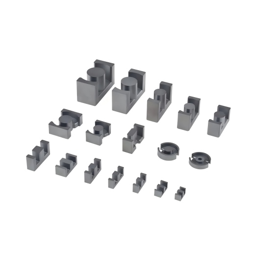
The three most commonly used soft magnetic materials for high-frequency transformers are: nanocrystalline materials, amorphous alloys, and ferrites. These materials have significantly different magnetic properties, and incorrect selection can lead to overheating, deterioration of EMI performance, and waste of costs.
Nanocrystals, amorphous materials, ferrites: How to choose the magnetic core materials for high-frequency transformers?
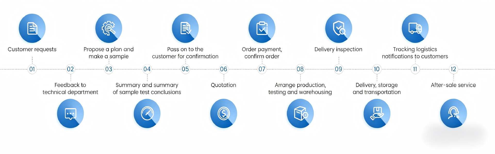
Customization of magnetic components starts with a customer providing a drawing or a set of parameters. From there, through multiple stages such as requirement communication, drawing review, material selection, winding and prototyping, tape wrapping and assembly, electrical testing, sample confirmation and packaging for shipment, the process involves numerous steps.
Customization process of magnetic component products: Comprehensive analysis from drawing to sample delivery.
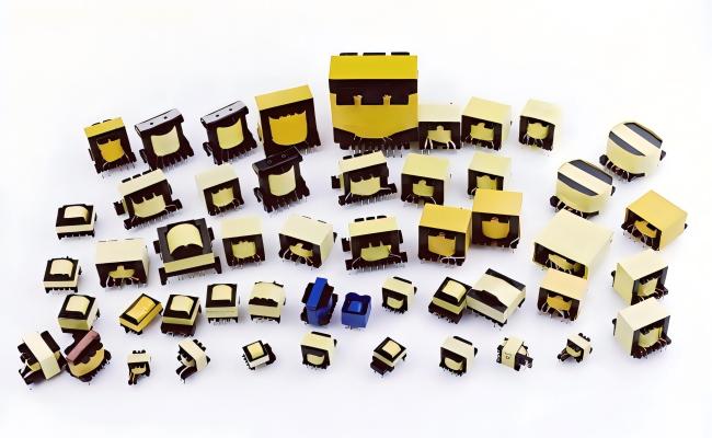
Practical SMPS transformer calculation tutorial. From parameter confirmation and core selection to winding, air‑gap and thermal verification for power supply design.
How to Calculate Switching Power Supply Transformers: A Complete Method from Parameter Determination to Core Selection

Customized magnetic components are not simple parameter adjustments; they are based on full-dimensional customized design of vehicle application scenarios, operating conditions data, and automotive standards, optimizing from material formulation, magnetic circuit structure, winding process, heat dissipation structure, protection system, and durability verification, completely solving the industry pain points of poor adaptability, short lifespan, and high failure rate of standard components.
How do custom magnetic components ensure longevity in harsh automotive environments?
SEND MESSAGE